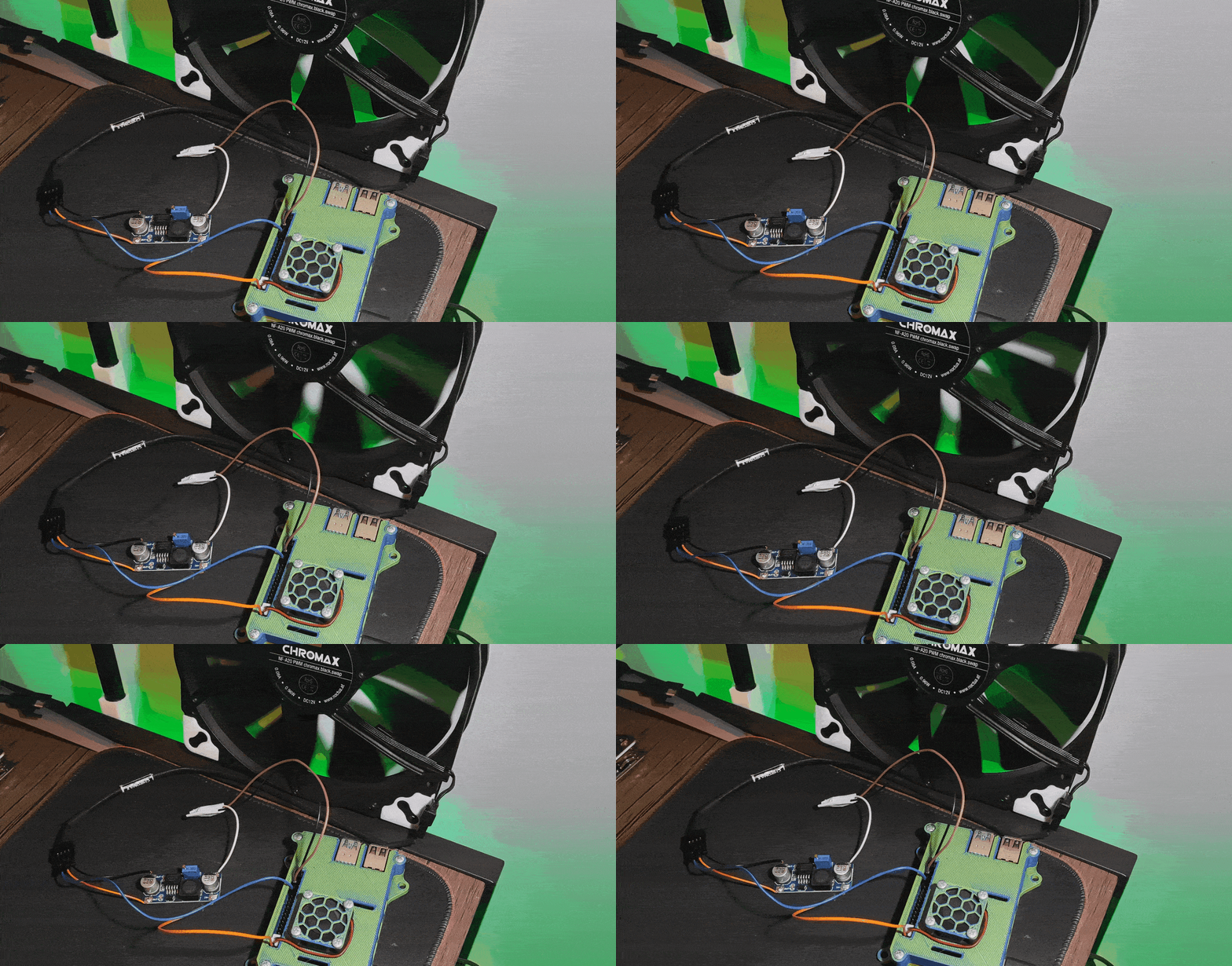
I am making my homelab and I need to control the Noctua NF-A20 PWM chromax.black.swap 200x200mm fan from Raspberry Pi, and this is how I’ve done it.
Parts you need:
- Some Raspberry Pi
- The Noctua NF-A20 PWM fan (should work with other 12V noctua fans as well)
- A multimeter
- LM2577 DC-DC Step Up Booster Converter
- NPN Transistor
- 1K Ohm Resistor
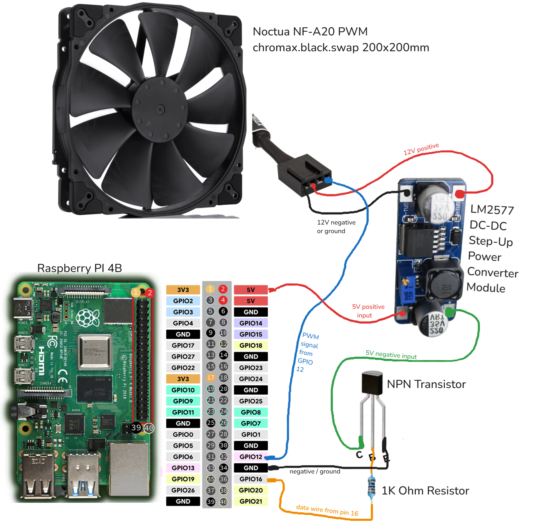
Diagram:
Let’s start from the Pi:
1- Connect a wire from GPIO pin 16, or any simple gpio pin, to the 1k resistor, and then the other end of the transistor to the middle pin of the transistor.
2- A wire from the right pin of the transistor to any ground pin of the Pi. The face of the transistor is the flat one.
3- A wire from the left pin of the transistor to the “IN-” 5V negative input of the power convertor.
4- A wire from one of the 5V Pi pins (top right) to the “IN+” 5V positive input of the power convertor.
5- Important: adjust the converter to 12V or lower.
Do NOT connect the fan right now because you can permanently damage it because of high voltage.
A- Turn on the converter by connecting a ground pin from the Pi directly to the Power Converter’s “IN-” connector OR by runing the code from the next section and just calling speed(fan, 100) / time.sleep(180).
B- Connect a multimeter to the converter’s “OUT+” and “OUT-” and select voltage measurement on the multimeter (usually marked as “2V”).
C- On the converter turn the small yellow screw until the multimeter shows 12V or a bit smaller to be safe. I have mine at 11.5V.
D- When you are done disconnect the multimeter and the ground wire, or turn off the script.
The pinout from the noctua fan I found here:
https://faqs.noctua.at/en/support/solutions/articles/101000081757-what-pin-configuration-do-noctua-fans-use-

5- Wire from power convertor “OUT-” (12V negative) to noctua pin 1.
6- Wire from power convertor “OUT+” (12V positive) to noctua pin 2.
5- Wire from noctua pin 4 to Pi GPIO pin 12. This pin has PWM capability .
The code:
I used the code from this tutorial published on the-diy-life.com by Michael Klements ( original code ), and I modified it to use the transistor to turn off the fan, because the fan PWM does not scale down to 0 RPM. The minimum rotational speed is 20% (350RPM).
 1#!/usr/bin/env python3
 2import RPi.GPIO as GPIO
 3import time
 4import signal
 5import sys
 6
 7# The Noctua PWM control actually wants 25 kHz (kilo!), see page 6 on:
 8# https://noctua.at/pub/media/wysiwyg/Noctua_PWM_specifications_white_paper.pdf
 9PWM_FREQ = 25           # [Hz] PWM frequency
10FAN_PIN = 12            # BCM pin used to drive PWM fan
11TRAN_PIN = 16           # NPN Transistor
12
13def speed(fan, percent):
14    print("set fan to", percent)
15    if (percent < 20):
16        GPIO.output(TRAN_PIN, False)
17        fan.ChangeDutyCycle(20)
18    else:
19        GPIO.output(TRAN_PIN, True)
20        fan.ChangeDutyCycle(percent)
21
22try:
23    signal.signal(signal.SIGTERM, lambda *args: sys.exit(0))
24    GPIO.setwarnings(True)
25    GPIO.setmode(GPIO.BCM)
26    GPIO.setup(TRAN_PIN, GPIO.OUT)
27    GPIO.setup(FAN_PIN, GPIO.OUT, initial=GPIO.LOW)
28    fan = GPIO.PWM(FAN_PIN, PWM_FREQ)
29
30    # do a few cycles just for testing
31    speed(fan, 100)
32    time.sleep(30)
33
34    speed(fan, 50)
35    time.sleep(30)
36
37    speed(fan, 0)
38    time.sleep(30)
39
40    speed(fan, 20)
41    time.sleep(30)
42
43    speed(fan, 70)
44    time.sleep(30)
45
46    speed(fan, 100)
47    time.sleep(30)
48
49except KeyboardInterrupt:
50    pass
51
52finally:
53    GPIO.cleanup()
Done. Happy tinkering !
Last modified on 2024-11-18


